Archive 19/01/2023.

Vertex Normals - 3 Sides of Cube not showing

vivienneanthony

Hey,

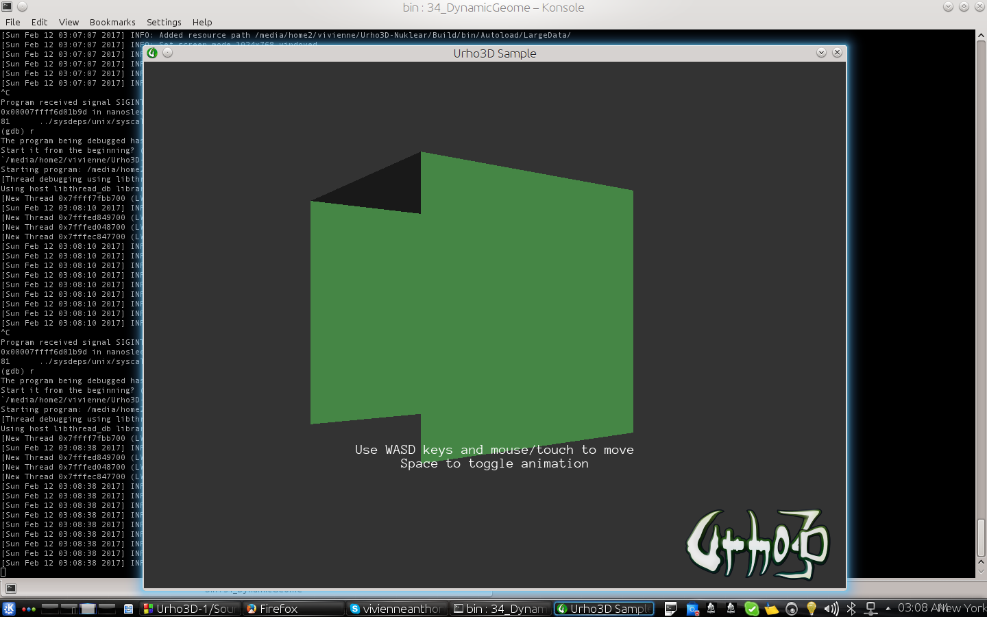
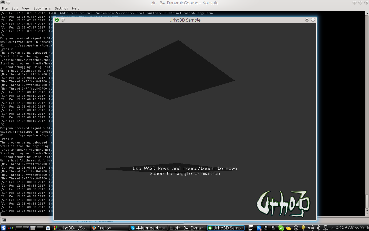
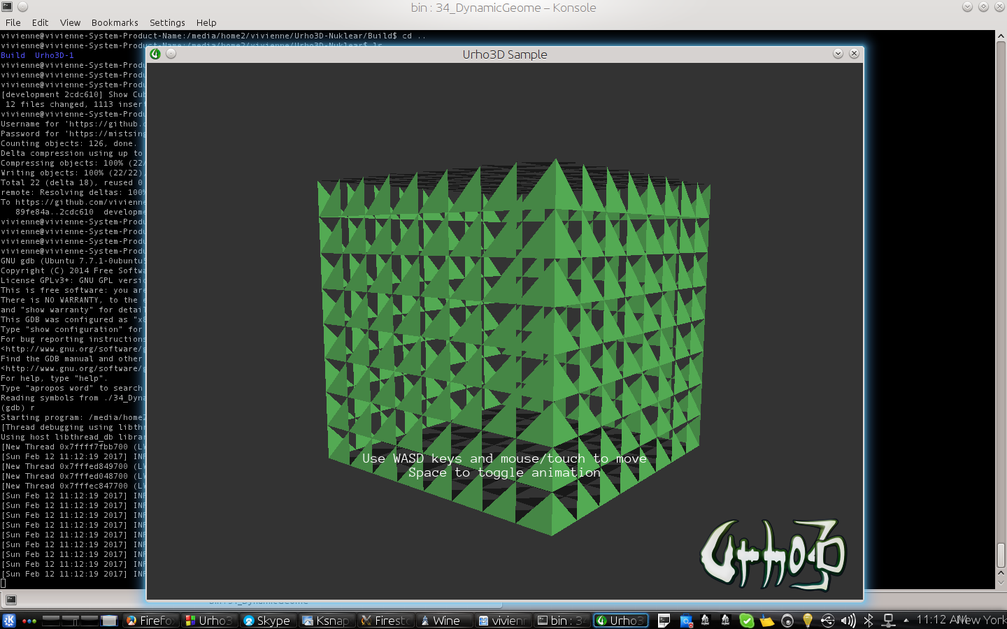
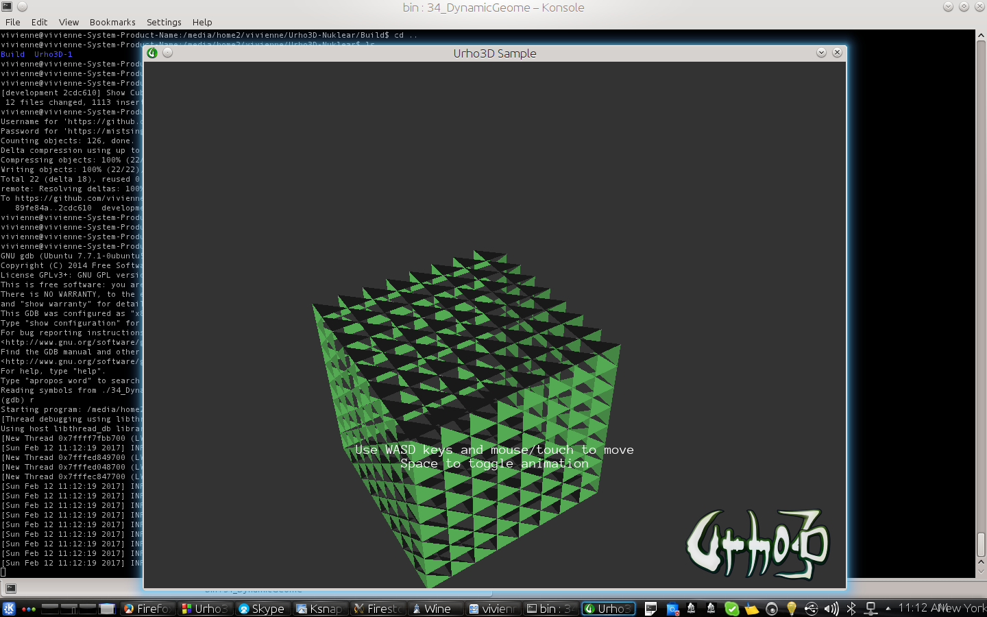
I have some code and it’s not showing 3 sides of a cube. I cannot figure what’s wrong. As I experminted with several ways. The code to produce the normal is right.

I’m going cut and paste the full code maybe someone can pick up on it.


void DynamicGeometry::CreateScene()
{
    ResourceCache* cache = GetSubsystem<ResourceCache>();

    scene_ = new Scene(context_);

    // Create the Octree component to the scene so that drawable objects can be rendered. Use default volume
    // (-1000, -1000, -1000) to (1000, 1000, 1000)
    scene_->CreateComponent<Octree>();

    // Create a Zone for ambient light & fog control
    Node* zoneNode = scene_->CreateChild("Zone");
    Zone* zone = zoneNode->CreateComponent<Zone>();
    zone->SetBoundingBox(BoundingBox(-1000.0f, 1000.0f));
    zone->SetFogColor(Color(0.2f, 0.2f, 0.2f));
    zone->SetFogStart(200.0f);
    zone->SetFogEnd(300.0f);

    // Create a directional light
    Node* lightNode = scene_->CreateChild("DirectionalLight");
    lightNode->SetDirection(Vector3(-0.6f, -1.0f, -0.8f)); // The direction vector does not need to be normalized
    Light* light = lightNode->CreateComponent<Light>();
    light->SetLightType(LIGHT_DIRECTIONAL);
    light->SetColor(Color(0.4f, 1.0f, 0.4f));
    light->SetSpecularIntensity(1.5f);

    // Get the original model and its unmodified vertices, which are used as source data for the animation
    Model* originalModel = cache->GetResource<Model>("Models/Box.mdl");
    if (!originalModel)
    {
        URHO3D_LOGERROR("Model not found, cannot initialize example scene");
        return;
    }


    // Finally create one model (pyramid shape) and a StaticModel to display it from scratch
    // Note: there are duplicated vertices to enable face normals. We will calculate normals programmatically
    unsigned numVertices = 18;


    // set chunks or patches
    int PatchSize=8;


    // Set Cube size
    float CubeSize=10;;

    // Get Cube Center - Create Defaults
    Vector3 center = Vector3::ZERO;
    Vector3 direction_x = Vector3::ZERO;
    Vector3 direction_y = Vector3::ZERO;


    // Create buffer
    Vector<Vector3> vertexData;
    Vector<unsigned short> indexData;

    // Create a index
    unsigned int index = 0;

    for(unsigned int face=0; face< 6; face++)
    {

        // Get Cube Center
        center = ((float)CubeSize/2)*TerrainFaceCoordinate[face];

        // Calculate direction based of x
        switch(face)
        {
        case Pos_X:
            direction_x = CubeSize*Vector3(0,1,0);
            direction_y = CubeSize*Vector3(0,0,1);
            break;
        case Neg_X:
            direction_x = CubeSize*Vector3(0,1,0);
            direction_y = CubeSize*Vector3(0,0,1);
            break;
        case Pos_Y:
            direction_x = CubeSize*Vector3(1,0,0);
            direction_y = CubeSize*Vector3(0,0,1);
            break;
        case Neg_Y:
            direction_x = CubeSize*Vector3(1,0,0);
            direction_y = CubeSize*Vector3(0,0,1);
            break;
        case Pos_Z:
            direction_x = CubeSize*Vector3(1,0,0);
            direction_y = CubeSize*Vector3(0,1,0);
            break;
        case Neg_Z:
            direction_x = CubeSize*Vector3(1,0,0);
            direction_y = CubeSize*Vector3(0,1,0);
            break;
        }

        // loop through and create a grid of vertices. // do not draw edge
        for (int u = 0; u < PatchSize; u++)
        {
            for (int v = 0; v < PatchSize; v++)
            {
                // Calculate patch size
                Vector3 x1=(direction_x / PatchSize) * (v- PatchSize / 2);
                Vector3 y1=(direction_y / PatchSize) * (u- PatchSize / 2);

                // Create the vertex grid around the center of thecube face (which is passed into the function as Vector3 center).
                Vector3 v1= center+ x1+y1;

                // Calculate patch size
                Vector3 x2=(direction_x / PatchSize) * ((v+1) - PatchSize / 2);
                Vector3 y2=(direction_y / PatchSize) * (u- PatchSize / 2);

                // Create the vertex grid around the center of thecube face (which is passed into the function as Vector3 center).
                Vector3 v2= center+ x2+y2;

                // Calculate patch size
                Vector3 x3=(direction_x / PatchSize) * (v- PatchSize / 2);
                Vector3 y3=(direction_y / PatchSize) * ((u+1)- PatchSize / 2);

                // Create the vertex grid around the center of thecube face (which is passed into the function as Vector3 center).
                Vector3 v3= center+ x3+y3;

                // Calculate patch size
                Vector3 x4=(direction_x / PatchSize) * ((v+1)- PatchSize / 2);
                Vector3 y4=(direction_y / PatchSize) * ((u+1)- PatchSize / 2);

                // Create the vertex grid around the center of thecube face (which is passed into the function as Vector3 center).
                Vector3 v4=center+ x4+y4;

                Vector3 n1;

                Vector3 edge1 = v4-v1;
                Vector3 edge2 = v3-v1;

                n1= edge1.CrossProduct(edge2);

                n1 = n1.Normalized();

                // store first triangle
                vertexData.Push(v1);
                vertexData.Push(n1);
                indexData.Push(index++);

                vertexData.Push(v2);
                vertexData.Push(n1);
                indexData.Push(index++);

                vertexData.Push(v4);
                vertexData.Push(n1);
                indexData.Push(index++);

                // another trianlge
                vertexData.Push(v4);
                vertexData.Push(n1);
                indexData.Push(index++);

                vertexData.Push(v3);
                vertexData.Push(n1);
                indexData.Push(index++);

                vertexData.Push(v1);
                vertexData.Push(n1);
                indexData.Push(index++);
            }
        }
    }
    numVertices = indexData.Size();

    SharedPtr<Model> fromScratchModel(new Model(context_));
    SharedPtr<VertexBuffer> vb(new VertexBuffer(context_));
    SharedPtr<IndexBuffer> ib(new IndexBuffer(context_));
    SharedPtr<Geometry> geom(new Geometry(context_));

    // Shadowed buffer needed for raycasts to work, and so that data can be automatically restored on device loss
    vb->SetShadowed(true);

    // We could use the "legacy" element bitmask to define elements for more compact code, but let's demonstrate
    // defining the vertex elements explicitly to allow any element types and order
    PODVector<VertexElement> elements;
    elements.Push(VertexElement(TYPE_VECTOR3, SEM_POSITION));
    elements.Push(VertexElement(TYPE_VECTOR3, SEM_NORMAL));


    vb->SetSize(numVertices, elements);
    vb->SetData(&vertexData[0]);

    ib->SetShadowed(true);
    ib->SetSize(numVertices, false);
    ib->SetData(&indexData[0]);

    geom->SetVertexBuffer(0, vb);
    geom->SetIndexBuffer(ib);
    geom->SetDrawRange(TRIANGLE_LIST, 0, numVertices);

    fromScratchModel->SetNumGeometries(1);
    fromScratchModel->SetGeometry(0, 0, geom);
    fromScratchModel->SetBoundingBox(BoundingBox(Vector3(-0.5f, -0.5f, -0.5f), Vector3(0.5f, 0.5f, 0.5f)));

    // Though not necessary to render, the vertex & index buffers must be listed in the model so that it can be saved properly
    Vector<SharedPtr<VertexBuffer> > vertexBuffers;
    Vector<SharedPtr<IndexBuffer> > indexBuffers;
    vertexBuffers.Push(vb);
    indexBuffers.Push(ib);

    // Morph ranges could also be not defined. Here we simply define a zero range (no morphing) for the vertex buffer
    PODVector<unsigned> morphRangeStarts;
    PODVector<unsigned> morphRangeCounts;
    morphRangeStarts.Push(0);
    morphRangeCounts.Push(0);
    fromScratchModel->SetVertexBuffers(vertexBuffers, morphRangeStarts, morphRangeCounts);
    fromScratchModel->SetIndexBuffers(indexBuffers);

    Node* node = scene_->CreateChild("FromScratchObject");
    node->SetPosition(Vector3(0.0f, 3.0f, 0.0f));
    StaticModel* object = node->CreateComponent<StaticModel>();
    object->SetModel(fromScratchModel);

    // Create the camera
    cameraNode_ = new Node(context_);
    cameraNode_->SetPosition(Vector3(0.0f, 2.0f, -20.0f));
    Camera* camera = cameraNode_->CreateComponent<Camera>();
    camera->SetFarClip(300.0f);
}

Vivienne

Eugene

Normals are unrelated to face visibility. Did you checked vertex order?

vivienneanthony

I am checking. I checked the code and looked up order. It’s partially better in which I can see all sides but one set of triangles seem inverse. When I flip the order a little it’s back to the same problem. So I need to read up on the order.

Right now the order is Triangle1(3 Vertex), Triangle2(3 Vertex).

/ Finally create one model (pyramid shape) and a StaticModel to display it from scratch
    // Note: there are duplicated vertices to enable face normals. We will calculate normals programmatically
    unsigned numVertices = 18;


    // set chunks or patches
    int PatchSize=8;


    // Set Cube size
    float CubeSize=10;;

    // Get Cube Center - Create Defaults
    Vector3 center = Vector3::ZERO;
    Vector3 direction_x = Vector3::ZERO;
    Vector3 direction_y = Vector3::ZERO;


    // Create buffer
    Vector<Vector3> vertexData;
    Vector<unsigned short> indexData;

    // Create a index
    unsigned int index = 0;

    for(unsigned int face=0; face< 6; face++)
    {

        // Get Cube Center
        center = ((float)CubeSize/2)*TerrainFaceCoordinate[face];

        // Calculate direction based of x
        switch(face)
        {
        case Pos_X:
            direction_x = CubeSize*Vector3(0,1,0);
            direction_y = CubeSize*Vector3(0,0,1);
            break;
        case Neg_X:
            direction_x = CubeSize*Vector3(0,1,0);
            direction_y = CubeSize*Vector3(0,0,1);
            break;
        case Pos_Y:
            direction_x = CubeSize*Vector3(1,0,0);
            direction_y = CubeSize*Vector3(0,0,1);
            break;
        case Neg_Y:
            direction_x = CubeSize*Vector3(1,0,0);
            direction_y = CubeSize*Vector3(0,0,1);
            break;
        case Pos_Z:
            direction_x = CubeSize*Vector3(1,0,0);
            direction_y = CubeSize*Vector3(0,1,0);
            break;
        case Neg_Z:
            direction_x = CubeSize*Vector3(1,0,0);
            direction_y = CubeSize*Vector3(0,1,0);
            break;
        }

        // loop through and create a grid of vertices. // do not draw edge
        for (int u = 0; u < PatchSize; u++)
        {
            for (int v = 0; v < PatchSize; v++)
            {
                // Calculate patch size
                Vector3 x0=(direction_x / PatchSize) * (v- PatchSize / 2);
                Vector3 y0=(direction_y / PatchSize) * (u- PatchSize / 2);

                // Create the vertex grid around the center of thecube face (which is passed into the function as Vector3 center).
                Vector3 v0= center+ x0+y0;

                // Calculate patch size
                Vector3 x1=(direction_x / PatchSize) * (v - PatchSize / 2);
                Vector3 y1=(direction_y / PatchSize) * (u+1- PatchSize / 2);

                // Create the vertex grid around the center of thecube face (which is passed into the function as Vector3 center).
                Vector3 v1= center+ x1+y1;

                // Calculate patch size
                Vector3 x2=(direction_x / PatchSize) * (v+1- PatchSize / 2);
                Vector3 y2=(direction_y / PatchSize) * (u- PatchSize / 2);

                // Create the vertex grid around the center of thecube face (which is passed into the function as Vector3 center).
                Vector3 v2= center+ x2+y2;

                // Calculate patch size
                Vector3 x3=(direction_x / PatchSize) * ((v+1)- PatchSize / 2);
                Vector3 y3=(direction_y / PatchSize) * ((u+1)- PatchSize / 2);

                // Create the vertex grid around the center of thecube face (which is passed into the function as Vector3 center).
                Vector3 v3=center+ x3+y3;

                Vector3 edge1 = v2-v1;
                Vector3 edge2 = v3-v1;

                Vector3 n1 = edge1.CrossProduct(edge2).Normalized();

                // order is wrong
                vertexData.Push(v0);
                vertexData.Push(n1);
                indexData.Push(index++);

                vertexData.Push(v1);
                vertexData.Push(n1);
                indexData.Push(index++);


                vertexData.Push(v2);
                vertexData.Push(n1);
                indexData.Push(index++);


                vertexData.Push(v1);
                vertexData.Push(n1);
                indexData.Push(index++);


                vertexData.Push(v2);
                vertexData.Push(n1);
                indexData.Push(index++);


                vertexData.Push(v3);
                vertexData.Push(n1);
                indexData.Push(index++);


            }
        }
    }
    numVertices = indexData.Size();

    SharedPtr<Model> fromScratchModel(new Model(context_));
    SharedPtr<VertexBuffer> vb(new VertexBuffer(context_));
    SharedPtr<IndexBuffer> ib(new IndexBuffer(context_));
    SharedPtr<Geometry> geom(new Geometry(context_));

    // Shadowed buffer needed for raycasts to work, and so that data can be automatically restored on device loss
    vb->SetShadowed(true);

    // We could use the "legacy" element bitmask to define elements for more compact code, but let's demonstrate
    // defining the vertex elements explicitly to allow any element types and order
    PODVector<VertexElement> elements;
    elements.Push(VertexElement(TYPE_VECTOR3, SEM_POSITION));
    elements.Push(VertexElement(TYPE_VECTOR3, SEM_NORMAL));


    vb->SetSize(numVertices, elements);
    vb->SetData(&vertexData[0]);

    ib->SetShadowed(true);
    ib->SetSize(numVertices, false);
    ib->SetData(&indexData[0]);

    geom->SetVertexBuffer(0, vb);
    geom->SetIndexBuffer(ib);
    geom->SetDrawRange(TRIANGLE_LIST, 0, numVertices);

    fromScratchModel->SetNumGeometries(1);
    fromScratchModel->SetGeometry(0, 0, geom);
    fromScratchModel->SetBoundingBox(BoundingBox(Vector3(-0.5f, -0.5f, -0.5f), Vector3(0.5f, 0.5f, 0.5f)));

    // Though not necessary to render, the vertex & index buffers must be listed in the model so that it can be saved properly
    Vector<SharedPtr<VertexBuffer> > vertexBuffers;
    Vector<SharedPtr<IndexBuffer> > indexBuffers;
    vertexBuffers.Push(vb);
    indexBuffers.Push(ib);

    // Morph ranges could also be not defined. Here we simply define a zero range (no morphing) for the vertex buffer
    PODVector<unsigned> morphRangeStarts;
    PODVector<unsigned> morphRangeCounts;
    morphRangeStarts.Push(0);
    morphRangeCounts.Push(0);
    fromScratchModel->SetVertexBuffers(vertexBuffers, morphRangeStarts, morphRangeCounts);
    fromScratchModel->SetIndexBuffers(indexBuffers);

    Node* node = scene_->CreateChild("FromScratchObject");
    node->SetPosition(Vector3(0.0f, 3.0f, 0.0f));
    StaticModel* object = node->CreateComponent<StaticModel>();
    object->SetModel(fromScratchModel);

    // Create the camera
    cameraNode_ = new Node(context_);
    cameraNode_->SetPosition(Vector3(0.0f, 2.0f, -20.0f));
    Camera* camera = cameraNode_->CreateComponent<Camera>();
    camera->SetFarClip(300.0f);
}

Lumak

This is what I’m seeing:

  1. 1st triangle: v0-v1-v2 -> clockwise winding order
  2. 2nd triangle: v1-v2-v3 -> counter-clockwise winding -> shouldn’t it be: v1-v3-v2 ?

edit: or you can set the material cull=“none”