Archive 19/01/2023.

How would I use Blender to load a model with more than one material?

Batch

I’m trying to learn the absolute basics of importing models into Urho3D. I made a cube in Blender, created two materials, made 5 faces blue and 1 face yellow, then tried exporting it. At first I ran into an error about BLEND files and parent relationships, and the solution online was to accept that BLEND files are not supported and instead export to FBX, then import FBX into Urho3D. I did that, but I can’t figure out how to set multiple materials on a StaticObject. The internet suggests telling Blender to export a materials list file, but I don’t see that option anywhere.

How should I go about loading a model with two materials into Urho3D such that I can programmatically construct a Node in C++, attach a StaticModel to it, then call functions that result in my test cube being rendered on screen with two different materials (i.e. 5 faces are blue, and 1 face is yellow)? Thanks.

throwawayerino

This is materials 101. In Blender you export to FBX (or anything else, FBX never fails though) and pass it to assimp. If blender shows it with two materials, the resulting mdl would have two material slots available. I’ve heard a long time ago going to edit mode->sort elements->sort by materials would fix any problems with ordering.
If you’re using the editor it should show two slots for inserting materials. You could insert them, save the node as an XML file, and load that instead.
If not, then calling StaticModel::SetMaterial() sets materials per slot
I think -l makes the importer write a material list and you could call StaticModel::ApplyMaterialList()


assimp broke with blender 2.8 and we’re waiting for upstream to fix it.

Modanung

I prefer using the add-on:

throwawayerino

Does reattiva’s addon still work? The 2.8 branch broke with me alot.

Modanung

I don’t update Blender. :+1:

1vanK

LitSolid and Unlit shaders by 1vanK · Pull Request #97 · reattiva/Urho3D-Blender · GitHub

Batch

Can you explain what a slot is and how I would go about determining the value to give it when calling StaticModel::SetMaterial?

Batch

What version of Blender is required in order to be able to use it with Urho3D?

Modanung

@reattiva ’s no greater than 2.79b.
@dertom ’s work is a fork/continuation which (only) works with 2.80 and beyond.

…and there’s @1vanK ’s fork, from the pull request he linked to:

evolgames

I use 2.9 of blender. Objs are fine. You don’t need to export anything special or any material lists, just the object. Make materials on faces like normal in blender. Use asset importer with -l flag. It’ll export .MDL and a .txt. That text file is the materials list. It MUST remain with the exact same name as the MDL to work. AssetImporter will also export the materials. To make things simple, have it export to your Data folder and those will be in the right spots (unless you have a different setup). Use ApplyMaterialList() and presto. It’ll be setup correctly. This is far faster than doing SetMaterial(slot, material), because it does it automatically for any number of materials. I’m literally doing this process right now for a bunch of models. I was never able to get the add-on to work since it isn’t updated for the newer blender version. I tried to update it myself but it didn’t work.

for example:

./AssetImporter model ~/model.obj ~/Urho3D/Projects/Game/Data/Models/hull.mdl -nt -l -h

and then (in lua)

local hullObject = node:CreateComponent("StaticModel")
hullObject.model = cache:GetResource("Model", "Models/hull.mdl")
hullObject:ApplyMaterialList(cache:GetResource("MaterialList", "Materials/hull.txt"))

You could also do

hullObject:SetMaterial(0, cache:GetResource("Material", "Materials/materialBlue.xml"))
hullObject:SetMaterial(1, cache:GetResource("Material", "Materials/materialGreen.xml"))
hullObject:SetMaterial(2, cache:GetResource("Material", "Materials/materialYellow.xml"))

This seems easy enough but if your model is even a tiny bit complex it’s a waste of time since the order of these materials isn’t clear. Plus this is doing exactly what the above does anyway, so you might as well do a material list if you have more than 1 material, especially since the lists can be generated while you create the .mdl anyway.

Batch

This is a fantastic answer! I also tried the addon without success, but generating the materials list via the importer was enough to get past the materials issue. I’m mostly guessing at how to get what I see in Blender into the game engine, and I had some issues with scaling and the physics isn’t quite right, but the cube is multi-colored! I even managed to update the exported materials xml files to use the highlighting stuff from Urho3DOutlineSelectionExample and it’s highlighting properly (mostly, see cloning issue below).

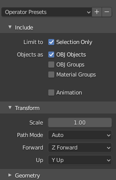
Do you have any suggestions for how to setup the FBX exporter, or using Blender in general, in order for me to get my cube to be the right size/scale, and have the foward and up faces be correct in the game world? I got better results when I used Apply Scalings: FBX Units Scale, but it’s just another guess.

Also, how would you manage materials that have shader settings which can change? In the Urho3DOutlineSelectionExample code it uses the Clone() method on the Material in order to allow individual shader parameters on each object in the scene such that you can highlight only one at a time. I had to add a cloned boolean to the Material object in order for this behavior to work with serialized scenes, and it wont be much effort to implement my own ApplyClonedMaterialList(), but I might be trying to fix a problem instead of doing things properly.

Thanks again!

evolgames

Glad it helped! The obj’s won’t have a scaling issue but fbx’s will be 100 times too big. I believe Unreal engine does the same thing.
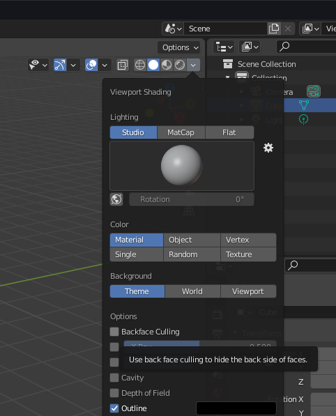
As far as faces, you’re going to want to model with “backface culling” so that if a face is facing the wrong way you’ll notice it and can flip the normal or recalculate the outside.

Or, you could set the material in urho to not cull the backside, which would also solve it. I use that for some models that the player will be inside of. You can set the below in the xmls, too, but I have so many this was just easier for now. The depth bias is to prevent Z-fighting, which you might run into later.

function MatCullDepth(staticObject)
	local i=0
	while staticObject:GetMaterial(i) ~= nil do
		staticObject:GetMaterial(i):SetCullMode(CULL_NONE)
		staticObject:GetMaterial(i).depthBias = Vector2(-.0001, -0.0001)
		i = i + 1
	end
end

I haven’t been using fbx, just objs, but I don’t apply scales or anything. I simply export my object at 1.0 and it’s fine in Urho. I imagine it’d be the same for fbxs, but you’d need to change the scale by a factor of 100. In blender, Z is up whereas in Urho it’s Y. Blender defaults to -Z forward so it’ll face the wrong way in Urho. Some people suggest parenting a node to your object that is rotated 180, but frankly it’s silly to do that to every model in your game. Better to just export as Z forward.

Screenshot_2021-04-26_09-45-06

Oh I see so if you apply all the materials but want to highlight the object you’d need to clone them or every other object gets highlighted. Well I’m not sure. I guess yeah you could make a function that cycles through each material (like above) and clones to apply the parameter. That’s probably what I’d do.

Batch

The only reason I was trying FBX was because I read in some other post that someone else used it with success. Switching over to Wavefront OBJ exports is even better! I managed to get Blender to think the cube is both 1m x 1m x 1m, and also a scale of 1.0, and now things are scaling properly and making sense within the Urho3D world. I actually managed to load up a model that I’ve failed to load numerous times so far, and it looks perfect - no sketchy texture flickering when it moves or other terrible problems from the past!

Do you have a suggested workflow for creating physics collision shapes in Blender that can be drawn on top of the model, then imported into Urho3D and used as the CollisionShape? If I go into blender and get the dimensions of the model, then I can hard-code something like this:

auto shape = node->CreateComponent<CollisionShape>();
shape->SetBox({ 2.16f, 2.4f, 5.95f});
shape->SetPosition({ 0.f, 1.2f, 0.f });

and I’ll get a box in the right position that covers the model, but it’s obviously not practical. I tried using the triangle mesh collision shape, but it nuked my framerate with just one object in the scene, so it seems like a no-go. If I could just draw some boxes in Blender that approximate the shape with rectangular prisms and spheres, that’d be all I need. However, the collision stuff in Blender seems intended for its own simulations, and not really for exporting.

Modanung

Maybe you could derive the collider(s’) position and dimensions from the model’s bounding box?

Batch

The bounding box would work in some cases, but I’m hoping for something a little more flexible. I can make a Cube in Blender that’s the same size as the collision box I want, and also in the right position relative to the model, so absolute worst case scenario I use Blender to find the size/position values of the collision geometries, then manually write xml files storing this information such that I can load the models into the game and have it automatically generate the compound shape behind the scenes using the xml files.

I think that workflow can be improved to the point where it’s no work at all, though. Learning how to use Blender better will make everything easier, but figuring out how to export just the information I need (or figuring out how to extract it myself via c++/python utilities) will make creating levels and objects super easy for me.

Maybe it’s possible to create my own option for the AssetImporter that knows to do something special when it encounters objects in the model file that have a special string in their name, and instead of exporting them along with the rest of the content it generates the aforementioned xml files using their geometries.

evolgames

Hmm have you tried shape:SetConvexHull(model)?

Modanung

The best approach likely depends on your specific usecase. Could you show some examples of the shapes you’re making and tell use how they interact?

Batch

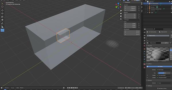
Here are some images of what I’ve been doing:

It shows the container model in Blender, as well as some cubes I made to act as collision shapes, then there’s a picture of the container’s convex hull debug draw, and then the custom cubes debug draw.

I had originally just used the Blender UI to get the width/height/depth and x/y/z values for the cubes I made, but I wanted something a little more automatic, so I threw together some python that generated some xml from obj files:

obj = read_wavefront(args.file)
for key, value in obj.items():
    print(f'Processing {key}')
    v = value['v']
    data = {
        'MinX': 99999,
        'MinY': 99999,
        'MinZ': 99999,
        'MaxX': -99999,
        'MaxY': -99999,
        'MaxZ': -99999,
    }
    for vertex in v:
        if vertex[0] < data['MinX']: data['MinX'] = vertex[0]
        if vertex[1] < data['MinY']: data['MinY'] = vertex[1]
        if vertex[2] < data['MinZ']: data['MinZ'] = vertex[2]
        if vertex[0] > data['MaxX']: data['MaxX'] = vertex[0]
        if vertex[1] > data['MaxY']: data['MaxY'] = vertex[1]
        if vertex[2] > data['MaxZ']: data['MaxZ'] = vertex[2]
    width = data['MaxX'] - data['MinX']
    height = data['MaxY'] - data['MinY']
    depth = data['MaxZ'] - data['MinZ']        
    x = data['MinX'] + width / 2.0
    y = data['MinY'] + height / 2.0
    z = data['MinZ'] + depth / 2.0
    x = -x
    print(f'<box width="{width:.2f}" height="{height:.2f}" depth="{depth:.2f}" x="{x:.2f}" y="{y:.2f}" z="{z:.2f}" />')

which generated this xml file for me:

<?xml version="1.0"?>
<shapes>
    <box width="0.30" height="0.50" depth="0.70" x="-1.25" y="2.27" z="1.87" />
    <box width="2.13" height="2.38" depth="5.94" x="0.01" y="1.20" z="-0.01" />
</shapes>

which I then load via:

XMLElement root = file->GetRoot();
if (root.GetName() != "shapes")
    return;

for (XMLElement element = root.GetChild("box"); element.NotNull(); element = element.GetNext("box"))
{
    auto shape = node->CreateComponent<CollisionShape>();
    shape->SetBox({ element.GetFloat("width"), element.GetFloat("height") , element.GetFloat("depth") }, { element.GetFloat("x"), element.GetFloat("y"), element.GetFloat("z") });
}

Convex hulls are a good alternative when I don’t need something specific, but I like being able to add specific CollisionShape component configurations graphically.

All in all I’m super happy with what I can do now using Blender and Urho3D.

Modanung

You could also do something like:

const BoundingBox bb{ model->GetBoundingBox() };
shape->SetBox(bb.Size(), bb.Center());

…to achieve the same result.

Batch

As mentioned previously the bounding box would work in some cases, but rarely is it acceptable when you want any kind of precision. Using multiple boxes is better.

Modanung

Sure, but the AC seems to be a separate model in this case. Also, I cannot judge the level of automation you’re looking for, based on a single screenshot. Are you aware an editor exists?

Batch

Even if the AC were a separate model the bounding box is too restrictive in that case. I’m not sure what kind of automation you’re talking about either… I wanted a way to import a model with several materials, to import a model and have it be the right scale/orientation, and to import CollisionShapes that were created in Blender alongside the model. With a lot of help from others I accomplished all of that.

There’s nothing left to solve.

Modanung

I thought I saw room for improvement: Based on the information you provided, the Python script and XML file seem needlessly convoluted.

Batch

It’s great that you’ve offered your opinion in an attempt to help. Keep it up!

The Python script and XML are rather simple and easy to understand. Having been thrown together quickly in an attempt to prove part of my desired workflow was feasible they’re naturally somewhat crude, but effective nevertheless.

Modanung

Yes, and in it’s current state ~two lines could do the same. But, have it your way, @Batch .

Batch

Two lines couldn’t do the same, as they would generate different collision geometries :slight_smile:

Modanung

Of course you can! Just leave out the newlines. :nerd_face:

As I understand your code, it finds a model’s bounding box and sets a box collider of that size.
Does it not?

Batch

You are quite wrong :slight_smile: Obviously if that were the case, then there would be only one geometry output from my script, but the screenshots I provided (along with describing it) show two geometries that almost perfectly align to the model.

Perhaps a re-reading of the post history will help you get out of this rut?

Modanung

No, I’ve seen the for s. Which - I assumed - went without saying, in light of my suggestion.
Did you read over the tilde in the “~two lines”? The model and the shape also drop out of nowhere.

Modanung

Let me put it this way: Two lines could replace ~95% of the code you showed.

Batch

Still quite wrong, friend :slight_smile:

The code I posted was Python, and depends on the wavefront_reader package. It goes on to crudely extract the bounding box and center position of each custom Cube it finds within the model file. This is the essence of the workflow I created where you can create Cubes in Blender that act as collision shapes for your model. A more robust version would of course account for rotation.

If you had posted code that extracted the bounding box and center position of the current object being parsed by the Python package wavefront_reader, then you’d have been much closer to being correct, as that would have yielded the same crude multi-geometry result I produced.