Archive 19/01/2023.

3D Intersection and HUD functionality? (Urho3D Beginner)

Kronix

Hello, I am considering using Urho3D with C# Visual Studio Xamarin.Forms to create an App that will be used on both Windows PCs and iPads. I would like to ask if Urho3D (Urhosharp) is the right choice for what I intend to make, as follows:

I need to build an app that checks whether machines of different sizes can fit into given spaces. I will represent the machines with simple objects like boxes, rhombohedrons, and cylinders. I will also be modeling rectangular rooms with 1 or 2 door openings, and the thickness of the walls must also be modeled. All these things are simple enough to be modeled with vertices directly in the code, and there will only be a small number of these template objects whose dimensions (including door placement and size in the case of rooms) will be changed by entering numbers for each object in text fields for each project.

I don’t want textures. The objects will be colored wireframes (blue, green, or purple) with translucent colored sides, so that I can see through them but still tell which side is facing me.

Here is the part that I am wondering whether Urho3D can do (Edit: Also wondering if the above colored wireframe + colored translucent sides is possible):

The objects can be moved around freely, and can move through each other. But whenever they move through each other, I want the intersection of the objects to be modeled in red. That is, the polyhedron that represents the 3d intersection of the objects should be colored with a red wireframe and red translucent sides. This way, I can see the intersection even if it is behind my line of sight.

Also, whenever an intersection occurs, I want a 2D yellow HUD reticle - either a circle or a rectangle - to bring attention to the intersection. This is like a targeting reticle in games or fighter jets, and it will change sizes to accommodate the size of the intersection, although it will have a minimum size so I can find intersections that might be very small. There can be multiple intersections and thus multiple reticles. I also want to be able to tap the display (or click in Windows) on the red intersection in the yellow reticle to bring up information about the objects that are intersecting – to be displayed on a side of the screen split from the rendering area – with the option to change the models’ sizes or position. It would also be nice if text labels would appear in the HUD for relevant objects, with a line pointing from the text to the object.

The intersections and reticles should appear, disappear, and mutate in real-time as I move machines around the room or change the dimensions of the room.

It would also be convenient to be able to rotate the model space by dragging and pinch to zoom in/out, although I will probably want to limit that to one axis at a time and I will have sliders as backup.

So my specific questions are:

  1. Can the 3D intersection be done in Urho3D?
  2. Can the HUD reticle (sized to enclose the intersection snugly) be done?
  3. Can the HUD text labels be done?
  4. Can I tap the screen to select the intersections?
  5. Can all of this be done with the rendering done on one side of the screen, and the data entry text fields for each object on the other side?
  6. Can all this be done in real-time?
  7. Can all the modeling be done in code without a separate CAD program?
  8. Will it be easy to develop and update this program in both iPad and Windows using all the same code?
  9. And of course, can it all be done easily? If not, can somebody recommend a better solution?

Edit 10. Can the colored wireframe rendering with translucent colored sides be done in Urho3d?

Thanks!

Modanung

First of all, welcome to the forums and congratulations on the longest post so far! :confetti_ball: :slight_smile:

Now I shall read.
EDIT: I will continue reading tomorrow.

lezak

Here are some suggestions:

  1. Yes, I think that the best way would be to cast rays between selected verticies (along the edges of
    the object), this will detect intersections and will give You positions that can be used to place verticies for creating object representing intersection;
  2. There are at least 2 options to do this - You can use Camera::WorldToScreenPoint method to place some ui elements or You can use bilboards and place them at the intersection;
  3. Once again at least 2 options: using ui + Camera::ScreenToWorld + CustomGeometry to draw lines or Text3D + CustomGeometry to draw lines pointing to the object
  4. Raycast to detect “intersetion” object or if You would decide to use ui elements to mark intersections, You can detect ui element under the cursor;
  5. You can use ui system and View3D object to place viewport wherever You want or You can change size and position of viewport You’ll be using to render and then place ui next to it (or over it);
  6. Yes;
  7. Once again yes: creating geometry in code is covered in sample 34_DynamicGeometry (in Urho, don’t how what samples are in Urhosharp). Basically You can create model from code by defining vertex and index buffers or use CustomGeometry component.
  8. This one I don’t know - I’m windows user, never had iPad in my hands;
  9. Well… I would risk and say yes, but You’ll have to spend some time to get familiar with Urho;
  10. Once again yes - for example debug geometry of NavArea is drawn this way, though it’s using DebugRenderer, You can get the genaral idea - use 2 geometries, first to draw “solid” walls (with unlit, transparent material) and second to draw lines along the edges. You can use DebugRenderer or CustomGeometry component to draw lines. Another approach would be to use 2 cameras from whom one will render in wireframe and then put image from one camera over the second (there should be some threads how to do this on the forum) - though I don’t know if result would be any good.
Kronix

Thanks a lot, it’ll take time to figure out all those solutions, but right now I’m wondering if you can provide examples of using raycasting for the intersection modeling in numbers 1 and 4. That was always the thing that appeared most difficult to me if there’s no prebuilt method. Let me pose a few conceptual questions about this before looking at how it might be coded:

A. From what I gather, every edge for every object in the scene will have to have a ray cast along it to make this work, and every one of those rays will have to be compared with every plane (mesh) for every object in the scene. Will that be a big performance hit?
B. Does Urho3D have the ability to treat an entire “side” as a plane for the purposes of the raytest, or do I have to test for every triangle in the mesh?
C. Can the raycasting determine the object that was hit?
D. After I determine the points of intersection, how will I know how those points should be connected to form the enclosed 3D intersection object? My first mathematical intuition is that all raycast points of intersection calculated from the same vertex must have an edge between them unless that new edge is broken by another (secondary test) raycast intersection along it.

Modanung

It can all be done.

To create the intersection meshes I think you should use something like CARVE . For the reticles you’re probably best off using a BillboardSet . There’s a sample demonstrating its use.

lezak

Octree raycast are quite fast in Urho, but of course performance would depend on complexity and number of objects. First thing to do would be setting custom view mask that would be used by ray to avoid unnecessary checks (for example against bilboards placed on intersections ).
Another thing is that there is no reason for every object to check for intersections all the time. Two quick ideas to limit number of checks:

  1. use physics and check for intersection only when object is colliding with another (using triggers will allow You to move one through another);
  2. using octree querries when some object is ‘active’ (moved or changed in some other way). You can use Octree:GetDrawables with BoxOctreeQuery to check if there are some objects intersecting with BoundingBox of this active object(s) and if there are some, do raycast only between them. In this case You wouldn’t have to do octree raycast, becasue You can call directly Drawable::ProcessRayQuery.
    If You are new to Urho and not familiar with it, I would suggest getting good look at: Octree , OctreeQuery , RayOctreeQuery , RayQueryResult (this one gives answer to Your C question) - for sure You’ll find something usefull there.
Kronix

Thanks, it looks like Carve CSG would do what I want and doing my own raycasting would be a waste of time. Can you give me some function names for collision/physics that I can research? I don’t see a reason why I would opt for the bounding box check if I can check for collisions directly.

If anybody comes up with some more alternatives I’m ears, I’m still getting accustomed to the code.

Sinoid

I’ll save you some time: if you use Carve CSG for what you describe you’re absolutely going to have to use Urho3D’s WorkItem and worker-threads to do the CSG in the background.

Before you add a task remove every CSG-task you can first - there’ll likely be one locked in flight so you’ll still get new stuff to render without flooding the worker-thread with a thousand CSG-tasks in the queue.

Carve is fast, but it’s not realtime fast. It’s definitely slower than bespoke CSG methods like that in Godot - but its’ advantage is being really easy to map to any kind of vertex data and triangle data (you can fake BSP in it very easily by tagging triangles to a surface).

Kronix

Yeah, Sinoid, that’s what I was afraid of. I’m wondering if I really need Carve. Is it possible to do one or both of the following without Carve?

A. Change the color of edges of an object that are within another to red. That means the line segments from the vertex of model A that is within model B to the points where each edge of model A first intersects the surface of model B will be colored red.

B. Create a HUD reticle that surrounds the intersection of the two objects, without actually rendering the intersection (and thus not needing Carve)?

I’m guessing if this is possible, it could be done with Urho3D’s built-in collision classes? But that’s just a guess. Can the collision classes help for objects/vertices that are already “inside” of each other?

Sinoid

There’s no easy way. You’re going to have to accept shortfalls or come up with ways to conceal things.

A. Change the color of edges of an object that are within another to red. That means the line segments from the vertex of model A that is within model B to the points where each edge of model A first intersects the surface of model B will be colored red.

You could add a depth-fail stage to the existing DebugRenderer class. Since the DebugRenderer is one of the last things drawn when a view is rendered you’ll have a complete z-buffer at that point and the depth-fail case will allow you to add lines for every edge in geometry that will only be drawn when they fail the depth test.

This won’t work if you need see those lines when you’re inside of the the geometry that should cause the depth-failure.

It also won’t work if you can have penetrations out of both view-facing and back-facing sides, all it can really do is say “I’m behind this”.

ie. it’ll mostly work if your program has a sort of lazy-Susan or can never enter the geometry behaviour.


Right now DebugRenderer only has no-depth and depth-test modes, that should be enough reference that adding a depth-fail would be fairly straight-forward - though sort of unpleasant because you’d break the interface (or just say screw it and do it as a switch “I’m in depth-fail mode! FTW!” .

B. Create a HUD reticle that surrounds the intersection of the two objects, without actually rendering the intersection (and thus not needing Carve)?

I think it was said before, but you could run raycasts along edges of one geometry against the other to check for intersections, if you’re looking at geometry that has relatively few polys that shouldn’t be bad at all, I’m picturing something simple like a crate pack .

In theory you could do Bokeh based on the results of a depth-fail addition to DebugRenderer, no idea how practical that would be, if the colors you want to draw for edges are reliably not colors that will be present in the models used then it’s really about how realiably you can get the bokeh point to be at the end-points. I think Bokeh are stupid though and have never touched them, so I have no idea how viable this would be.

I’m guessing if this is possible, it could be done with Urho3D’s built-in collision classes? But that’s just a guess. Can the collision classes help for objects/vertices that are already “inside” of each other?

No, collision in 3d is done via Bullet. It’s fairly naive and doesn’t have the information you want with any degree of reliability because it uses a moving manifold . You could try drawing the manifold points, but they might not be stable from frame-to-frame.

Kronix

I suppose I could use lezak’s two suggestions above for finding intersection locations for the HUD reticle? He mentioned Octree BoundingBox as well as this:

Which classes should I be looking at for this?

I assume his suggestions are easier than raycasts. He only mentioned raycasts for Octree for manually modelling the 3d intersection, which I already decided was too complex. I just want something for determining the HUD reticle.

Sinoid

Trigger is a part of RigidBody .

You’re going to have dredge through the forums or experiment yourself, as I can’t recall what events trigger-bodies send. They don’t send all of them IIRC.

Several RigidBody related events have a P_CONTACTS field of their event data that you can read to get a list of position+normals for contact pointers. They aren’t guaranteed to be stable, but they’re usually close.

Kronix

Hi again, I’ve been working on my project and have a few questions:

  1. What is the difference between Geometry and CustomGeometry classes? As it is, I’m just feeding the VertexBuffer into my Geometry class, and Geometry into the Model Class. CustomGeometry seems to be used exactly the same way in examples I’ve seen.

  2. Where can I get an explanation of the options for Material.SetTechnique() and what the defaults are if I don’t use it?

  3. Why do my Urho.Color RGBA colors always seem to lock into a solid primary color? For example, if putting in (1,250,1,0.8) produces the same color as (1,150,1,0.8), and if all the numbers are small, I always get grey.

  4. Where can I get a sample of how pop-up Message Boxes are used in Urho?

Dave82

Color values should be normalized.Don’t use greater values than 1.0f because they’re most likely clamped between 0.0f and 1.0f Examples:

Color(1.0f , 0.0f , 0.0f , 1.0f) // Full red
Color(0.0f , 1.0f , 0.0f , 1.0f) // Full Green
Color(1.0f , 0.5f , 0.0f , 1.0f) // Orange
Sinoid

CustomGeometry just wraps everything together and uses a simpler interface for defining the geometry and getting it setup to render as a Drawable .

If you go the raw route you have to setup a static/animated model component and give it your created model and when creating the vertex-buffers you need to be aware of the vertex-layout/etc. The more important thing is that the Model resource you create when going the raw-route is reusable (ie. you’ve loft a column mesh and want to use it a whole bunch).

You use whichever you want to for the most part - CustomGeometry 's only caveats are that it isn’t setup to share the geometry with anything else and can’t setup bones/weights/morphs - which you may or may not care about.

Kronix

Dave82, I’ve discovered the following using my eyes:

If I only set the material this way: Material material = Material.FromColor(myColor);

before assigning it to the StaticModel, then the maximum values for each RGBA field appear to be 10.0f. That is, (10,0,0,1) produces the brightest red, (150,0,0,1) produces the same brightest red, and (9,0,0,1) produces a slightly darker red. The fourth value can be adjusted between 0 and 1 to change the alpha blend.

However, if I add these two lines before assigning to the StaticModel:

material.SetTechnique(0, CoreAssets.Techniques.NoTextureUnlit, 1, 1);
material.LineAntiAlias = true;

then the maximum RGBA values become 1.0f. So (1,0,0,1) produces the brightest red, (15,0,0,1) produces the same brightest red, and (0.9,0,0,1) produces a slightly darker red. However, using this second way, I can’t alpha blend, so (1,0,0,0.2) would produce the same opaque brightest red.

Same goes for combinations: (10,10,0,1) produces the brightest yellow in the first example, (1,1,0,1) produces the brightest yellow in the second example.

Can somebody explain this?

Dave82

Again , you should ALWAYS use values between 0.0f and 1.0f, If you use greater values than 1.0f even God couldn’t predict how will this value end up on your screen.
Is it clamped by Urho3D ? Is it clamped by a shader ? Does the graphics API handle this ? If it does , is there a difference between OGL and DX9 DX11 , etc how to handle this situation ?
maybe @Sinoid could explain what happens if your color values are not in a normalized range.

AFAIK alpha blending will not work out of the box .Try using NoTextureAlpha or NoTextureVCol techniques for vertex alpha blending.

Sinoid

The range is 0 - 1.

Vertex data

In the vertex-data colors are sent a unsigned normal bytes, with a range of 0 - 255 which because the vertex semantic says that it’s an unsigned normal it gets interpreted as the 0-1 range that the shader needs (if sent as a plain ubyte4 it’d have to be divided, which would be a wasteful division).

The floating point color is converted to ubte4 by:

unsigned Color::ToUInt() const
{
    auto r = (unsigned)Clamp(((int)(r_ * 255.0f)), 0, 255);
    auto g = (unsigned)Clamp(((int)(g_ * 255.0f)), 0, 255);
    auto b = (unsigned)Clamp(((int)(b_ * 255.0f)), 0, 255);
    auto a = (unsigned)Clamp(((int)(a_ * 255.0f)), 0, 255);
    return (a << 24) | (b << 16) | (g << 8) | r;
}

which brings the values up into the 0-255 byte range and packs them. Notably, they’re clamped and must be since a unorm ubyte4 can’t go outside of the 0-1 range, otherwise they’d wrap around. So in vertex-data, colors outside of the range are pointless.


Uniforms / CBuffers

Colors passed to uniforms/c-buffers/material-variables are sent as regular float4s and are still expected to be in their normalized range (you would deviate if doing HDR/rgbm/etc).


It’s the vertex semantics that matter, so if you really really wanted to be using 0-255 ranged colors for some reason you can change you how construct the vertex-buffers (use a different type and something other than Color). It’ll then fall on you to do the division in the shader to get it into the 0-1 range that the graphics-API, lighting-functions, etc (basically everything) expects. Or leave things as is, but use your own unsigned char[4] color type.

Kronix

Thanks, but what could be causing my colors to only reach maximum brightness when I set the value to 10.0f then as stated in my post above? 1.0f only gives me 10% color, which is very dark. Besides when using the default settings (when no SetTechnique is set), I’ve found that CoreAssets.Techniques.NoTextureAlpha also requires 10.0f for brightest color. Even Peek Definition shows me the comments in the definition of the Color class telling me the values should be between 0 and 1, but my own eyes are telling me I only get maximum color at 10 (and going above that doesn’t change anything).

What is this HDR/rgbm/etc deviation you speak of?

Sinoid

Thanks, but what could be causing my colors to only reach maximum brightness when I set the value to 10.0f then as stated in my post above?

You mentioned that you were creating the vertex-buffers yourself, can you post your VertexBuffer::SetSize call (and the data you feed it)? It’ll be something looking like this:

vertBuffer->SetSize(vertexData.Size(), {
                { TYPE_VECTOR3, SEM_POSITION },
                { TYPE_VECTOR3, SEM_NORMAL },
                { TYPE_VECTOR4, SEM_TANGENT },
                { TYPE_VECTOR2, SEM_TEXCOORD }
            }, false);

… what we need to see is how you’ve setup your SEM_COLOR value. It is possible to set it up such that you’re able to go outside the normal range, but we’d have to see your code to know you’ve done that (ie. { TYPE_VECTOR4, SEM_COLOR } ).

Seeing how you set the value of a vertex in the buffer (don’t need the whole code, just whatever loop sets the buffer-data) would be useful as well. You shouldn’t be able to go outside of the 0-1 range unless you have intentionally or unknowingly set things up so that you can (there isn’t a right/wrong to it, it just makes it really hard to communicate what’s going on if it’s non-standard).

1.0f only gives me 10% color, which is very dark.

You’re using alpha right? What’s your alpha value? You can’t hold the same value and have transparency, the alpha will make it appear darker.

When you’re getting the value your eyes say is correct are you also losing any transparency you previously had?

Screenshots would really help here.

What is this HDR/rgbm/etc deviation you speak of?

It’s not what you need, it’s using real-world or extended units for lighting/color/etc. A discipline in itself.

Kronix

First I must admit my code is in C# with UrhoSharp so I hope you don’t abandon me :frowning: . I tried duplicating the color assignment in C++ DynamicGeometry but ran into the problem that the C++ version doesn’t seem to have equivalent code to this:
Material material = Material.FromColor(solidColor);
material.SetTechnique(0, CoreAssets.Techniques.NoTextureAlpha, 1, 1);
edge.SetMaterial(material);

namely the FromColor method in the library. How does C++ assign the material color? Once I find that out I can try duplicating the problem in C++.

Edit: If I use material.SetTechnique(0, CoreAssets.Techniques.NoTextureUnlit, 1, 1); then all the RGB values work between 0 and 1, but the alpha blend does not work and the surface is always solid.

solidColor was passed to the function, so it is something like new Color(5f,7.5f,1f,0.2f) . That produces a greenish yellow translucent surface. The alpha works fine, and is still between 0 and 1. I actually use alpha of 1 with the same color and similar code to produce the wireframe around the solid using line vertices (groups of 2) instead of triangle vertices (groups of 3).

In the meantime here’s the C#:

My Vertex Buffer looks like this:

    List<VertexBuffer.PositionNormal> triVertices = new List<VertexBuffer.PositionNormal>();
    triVertices.AddRange(axisVertices);

    VertexBuffer edgeBuffer = new VertexBuffer(Urho.Application.CurrentContext, false);
    edgeBuffer.SetSize((uint)triVertices.Count, ElementMask.Position | ElementMask.Normal, false);
    edgeBuffer.SetData(triVertices.ToArray());

The Vertices were defined as follows (this is just a small piece of about 100 vertices):

    VertexBuffer.PositionNormal[] axisVertices =
    {
        new VertexBuffer.PositionNormal
        {
            Position = new Vector3(-1f,0,0)
        },
        new VertexBuffer.PositionNormal
        {
            Position = new Vector3(-0.5f,2.1f,0)
        },
        new VertexBuffer.PositionNormal
        {
            Position = new Vector3(-0.5f,0,0)
        },
        new VertexBuffer.PositionNormal
        {
            Position = new Vector3(-1f,0,0)
        },
        new VertexBuffer.PositionNormal
        {
            Position = new Vector3(-1f,2.1f,0)
        },
        new VertexBuffer.PositionNormal
        {
            Position = new Vector3(-0.5f,2.1f,0)
        },
  }
Dave82

material->SetShaderParameter(“MatDiffColor” , yourColor);

Kronix

I’ll try using that later. For now I have a different problem. My translucent objects randomly become lighter in color when they move up or down through other translucent objects, and only the parts that blend (overlap) with the other objects. When I say lighter, I mean even more so than the correct blend. The error depends on a combination of the position of the objects and the position of the camera, so just changing the camera angle can make it temporarily disappear. Is this a known problem? Also, I have not defined any light nodes and am using NoTexture with Alpha. Does Urho create a LightNode on its own by default that could be causing this?

Dave82

I already mentioned this issue before , unfortunately the devs couldn’t reproduce it. it has to do something with manual material creation…

No. Urho does not add anything by default to a scene.

Kronix

Thank goodness, that means I’m not crazy. I’m not even using textures though and my program is still very simple, just translucent colored boxes (actually rooms with interior walls) out of meshes and wireframes out of lines. I’ve noticed that sometimes the meshes will change color separately from the wireframe, but it is only noticeable if you move the camera by a single degree or so, otherwise it appears to happen simultaneously. It also does not happen if I move the objects so they are not overlapping.

I can’t imagine somebody having difficulty reproducing this.

Modanung

@Kronix & @Dave82 Are you running similar hardware and drivers?

Kronix

I’m running Android 8. It happens in Emulator and on Samsung device.

Edit: One thing I just noticed is that the wireframes, which have alpha blend set to 1, are still blending with the translucent box behind (inside) it, and this is happening the majority of the time. In the moments where the box inside becomes lighter, the wireframe is showing full color as it’s supposed to. Which leads me to believe that the temporary lighter flicker is the engine doing what it’s supposed to instead of the other way around.

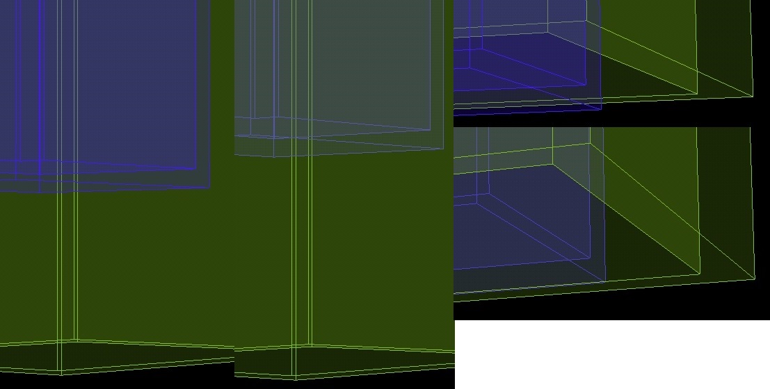
2nd Edit: Screenshots. alphaerror2

The blue box is inside the yellow-green box. On Exhibit A (left) the blue box was moved up a bit. On Exhibit B (right) the camera was moved up a bit. On Exhibit B the green box is open on the bottom so you’re seeing the
bottom of the blue box in the foreground only blended with the back of the green box behind it (in case the perspective is confusing). The lighter blue color is the color that it flickers to, normally it is the darker.

Edit3: Notice in the top of Exhibit B, the vertical wireframe lines of the blue box are drawn in front of the green wireframe, even though those green lines are supposed to be in the foreground. Remember, this is what it normally is, not what it flickers to. Same goes for the horizontal lines in the left of Exhibit A, although only the left pair of green wireframe lines are supposed to be in the foreground, the right two are in the back behind the blue box. Hmm, but it looks like the light blue box wireframe in Exhibit A is also incorrectly drawn in front of green lines. Not so in Exhibit B though, that is correct.

Sometimes, rarely, I see the green wireframe showing full color on top of the darker blue box without the blue box becoming lighter. Shouldn’t the wireframe that’s in front of the blue box always show full color? Sometimes I even see the vertical green wireframe in the back being completely hidden by the blue box (but still being shown above and below the blue box).

SirNate0

If they’re both alpha blended materials (which I believe will be the case whenever one of the alpha materials is used, independent the alpha blend being set to one) I think there will be flickering as you described based on which object ends up being sorted on the CPU as being closer to the camera. I’m not really sure of any of that, but I think I ran into a similar problem once that I avoided by forcing one of the object to always be slightly closer to the camera.

Kronix

@SirNate0 Well, in this case one box is inside the other. If Urho can’t detect which is closer, that means it’s doing Z-Buffering on a model basis instead of a mesh (per triangle) basis. I’m no expert on the topic, but I think that is a couple decades out of date.

Anyway, I have two new questions which aren’t really about this alpha blending problem, but coincidentally sound the same:

  1. Sometimes two models can have exactly the same geometries in exactly the same positions. In this situation it seems that the colors displayed (both solids and wire frames) are random. So if I had something like, say, a 3D progress bar (rectangular cuboid), with a maximum bar colored blue and the percent complete bar colored red and gradually becoming the same size as the blue bar, how do I tell Urho that the red bar should in effect be drawn last so that no blue shows up at random in the part that is complete?

  2. If object A is behind object B, and object B is either alpha blended or opaque, this will either change the color of object A or make object A invisible. How do I tell Urho to ignore this and show object A as if nothing was in front of it. What I mean is, how do I tell it to ignore Z-Buffer for specific objects?

SirNate0

This article is old, so it’s possible not all of it’s correct, but this might give some insight into the problems in properly sorting alpha blended objects (though unfortunately the image links seem broken now, but the text should give you a decent enough idea) https://blogs.msdn.microsoft.com/shawnhar/2009/02/18/depth-sorting-alpha-blended-objects/ .
I think this thread probably has enough info about controlling the render order How to control render order .
Sorry I can’t be more helpful, but I really don’t know all that much about the intricacies of graphics programming…

Dave82

@Modanung I’m using a GT 430 but had the same issue on my other GPUs too.

Kronix

@SirNate0 thanks, SetRenderOrder was what I needed. After a small panic not being able to access it in C# and looking through the DLL bindings, I found it was implemented as a private function encapsulated in the RenderOrder property. Seems to work beautifully now :kissing_heart:

Why and when do they decide to make such modifications when porting the engine?

Kronix

Another question: How do I make Urho interact with the GUI that contains it? For example, if it is a surface in Xamarin.Forms how would I make a camera movement in Urho change the color of a button in Xamarin?

I’m sure there’s a simple answer to this I’m missing.

Modanung

That sounds like something that would be better to ask on the Xamarin forums ?

I3DB

UrhoSharp.SharpReality does, as shown in the code for StereoApplication.cs .

Kronix

Simple Question: How do I tell if an angle between two Vector3’s is greater than 90 degrees? CalculateAngle only returns values between 0 and Pi / 2.

I want to prevent my camera from revolving past the top or bottom vertical.

Edit: And is there a function to rotate a point defined by a Vector3 using a Quaternion, returning a new Vector3? That way I can test where the camera will be after rotation, before I actually rotate it.

Modanung

Vector3::Angle(const Vector3& rhs) returns the angle in degrees instead of radian s like this CalculateAngle function - which is not a part of Urho3D - seems to do.

In the samples clamping the camera pitch is handles this way:

// Mouse sensitivity as degrees per pixel
const float MOUSE_SENSITIVITY = 0.1f;

// Use this frame's mouse motion to adjust camera node yaw and pitch. Clamp the pitch between -90 and 90 degrees
IntVector2 mouseMove = input->GetMouseMove();
yaw_ += MOUSE_SENSITIVITY * mouseMove.x_;
pitch_ += MOUSE_SENSITIVITY * mouseMove.y_;
pitch_ = Clamp(pitch_, -90.0f, 90.0f);

// Construct new orientation for the camera scene node from yaw and pitch. Roll is fixed to zero
cameraNode_->SetRotation(Quaternion(pitch_, yaw_, 0.0f));

You can rotate a Vector3 by multiplying it with a Quaternion , which makes perfect mathematical sense.

Kronix

VecQuatMultiplyFail

:disappointed_relieved:
I knew Urhosharp wasn’t as mature as Urho3D, but dang…

Also I’m talking about revolving the camera like the moon around the earth, but only within 180 degrees to the y axis. Not regular rotation, I’m using cameraNode.RotateAround(Vector3, Quaternion). I see there’s a Vector3 clamp function, but I don’t think that will work in this situation (180 degrees). I’m not even sure it works according to angle in the first place.

Modanung

Right, it’s Quaternion * Vector3 , not the other way around.

Kronix

:see_no_evil:

ok thanks. c++ example of 180 degree vector clamping would also be appreciated :nerd_face:

Modanung

Does the sample code I posted earlier not work for you?

Kronix

No, your code rotates the camera. I want to move the camera by revolving it (the moon) around a center point (the earth). Luckily, Urhosharp contains a cameraNode.RotateAround(Vector3, Quaternion) that automatically rotates the camera to keep the camera pointing at the Vector3 point while simultaneous REVOLVING the camera around the point using the Quaternion, keeping the same distance.

But I need to test that the camera doesn’t rotate (Edit: I mean REVOLVE, not rotate, since the rotation happens automatically) around the top or bottom past the y axis of the center point, or else the camera and image will be upside down. That’s why I wanted to test the movement of the camera in advance by assigning it to a Vector3 and rotating that using Quaternion multiplication and canceling the camera rotation if it moves past the axis. Still difficult, since direct multiplication requires me to calculate the rotation axis at any point, instead of letting RotateAround do it for me.

I’m still not sure if it’s easily possible to do this when I can only calculate angles within 90 degrees, since I can’t tell which side of the axis a given degree (for example 89 degrees) is. But c++ code using over 90 degrees could still help.

Modanung

Try adding a SetPosition(targetPosition - cameraDirection * distance) after setting the rotation.

Kronix

So I want to select 3D objects in my android app using touch. So if Box A is the main object and inside Box B, when I touch Box A it will be highlighted even though it is bound inside Box B. But if I touch it again it will be intelligent and know I want to select Box B instead (because the wall of Box B is between my finger and Box A).

So a simple task that has been done many times before. lezak mentioned in a post above to use raycasting. Anybody have some tips and examples to start? Can be mouse click instead of touch.

I3DB

I explored raycasting a bit here .

The goal for that was to be able to raycast individual components and leave them in a raycasted state where their own processing routine takes over to determine when the component can again be raycasted, and what to do once raycasted.

This pattern worked well for my individual case, but likely will need adjusted for other uses.

Also, I queued up raycast events to do all the processing possible on background threads, but while awaiting the various queued events to be processed, didn’t want the same object again raycasted, with another event for it queued up.

The physicsworld component also offers spherecast and convexcast.

Also, just reviewing that pattern again now realize that the update should change the viewmask before queueing it up, and therefore can continue to raycast immediately, rather than inserting a .1 second delay.

Kronix

I can’t get this raycasting stuff to work. RaycastSingle always returns null and Raycast always returns a 0 size List. I thought it’s supposed to return the drawable of the node of the first triangle it hits in the direction of a Ray? Do I need to make a certain Bounding Box? I only have Bounding Boxes for all my Geometry’s and they’re (-10,-10,-10) to (10,10,10). But I noticed the objects disappear when I zoom in if I make the Bounding Boxes smaller.

I3DB

Be sure your raycast distance is adequate for object placement. Maybe the objects are 10f away, and you are raycasting only 5f. Or perhaps the masks are set to not be raycasted.

RaycastSingle returns a single object or none, if the objects are within distance and can be raycasted.

Modanung

@Kronix Could you maybe share some of your ray casting code?

Kronix
TouchState state;
Vector3 hitPos;
Drawable hitDrawable;

if (input.NumTouches > 0) state = input.GetTouch(0); else return;
IntVector2 pos = state.Position;
Ray cameraRay = camera.GetScreenRay((float)pos.X / Graphics.Width, (float)pos.Y / Graphics.Height);
var result = scene.GetComponent<Octree>().RaycastSingle(cameraRay, RayQueryLevel.Triangle, 250f, DrawableFlags.Geometry);
if (result != null)
{
                hitPos = result.Value.Position;
                hitDrawable = result.Value.Drawable;
                hitDrawable.Node.Translate(new Vector3(0.1f, 0, 0));
}

It should move a box to the right when I touch it. My camera is 20 units back. The models have a bounding box from (-10,-10,-10) to (10,10,10), although the models themselves are only from (0, 0, 0) to about (2, 2, 3). result is always null! I haven’t changed any ViewMasks anywhere in my code.

Modanung

I’m used to these ray cast methods accepting RayOctreeQuery& s. Which includes a PODVector<RayQueryResult>& . This could be a Xamarin bug for all I know.
What’s the return type of this RaycastSingle function you’re using?

Kronix

raycastsingletype
raycasttype

'tis indeed RayQueryResult

Edit: Are BoundingBoxes necessary for raycast? And do I only need to set them for the Model object? Does Model.NumGeometries matter?

Edit: Here’s my code for creating the objects. Nothing here preventing raycasting, right?

            VertexBuffer edgeBuffer = new VertexBuffer(Urho.Application.CurrentContext, false);
            edgeBuffer.SetSize((uint)triVertices.Count, ElementMask.Position | ElementMask.Normal, false);
            edgeBuffer.SetData(triVertices.ToArray());

            Geometry edgeGeometry = new Geometry();
            edgeGeometry.SetVertexBuffer(0, edgeBuffer);
            edgeGeometry.SetDrawRange(PrimitiveType.TriangleList, 0, 0, 0, (uint)triVertices.Count, true);

            Model edgeModel = new Model();
            edgeModel.NumGeometries = 1;
            edgeModel.SetGeometry(0, 0, edgeGeometry);
            edgeModel.BoundingBox = new BoundingBox(new Vector3(-10, -10, -10), new Vector3(10, 10, 10));

            mainNode.RemoveChild(mainNode.GetChild("edgeNode1"));
            Node edgeNode = mainNode.CreateChild("edgeNode1");
            StaticModel edge = edgeNode.CreateComponent<StaticModel>();
            edge.Model = edgeModel;

            Material material = Material.FromColor(solidColor);
            edge.SetMaterial(material);

Edit: Added a plane using CoreAssets.Models.Plane and the raycast to the plane works, but still not the others created using Vertices. Here’s the code I added. Why would it work for this but not the above code?:

Node planeNode = mainNode.CreateChild("planeNode1");
var plane = planeNode.CreateComponent<StaticModel>();
plane.Model = CoreAssets.Models.Plane;
I3DB

Just reviewing my code, and everything I raycast is a static model or animated model (inherits static model). When something isn’t detected, it’s usually because I’ve set viewMask or the ray is missing the object for some reason.

You could set a staticmodel in same place as that object and see if it detects.

Kronix

Did you see the last edit in my previous post? It looks like all of your models are loaded pre-made. Is it possible that manually created models like mine have a different default ViewMask?

I3DB

Set the viewMask for both the raycast and the object, just to be sure.

Kronix

Already tried that. I tried setting some to 0x70000000 and some to 0x60000000 and tried setting the Raycast ViewMask to both of those, no effect.

I3DB

Perhaps put in some big floating objects, like cubes. Get that working, then revert to your custom geometry? If the plane raycast works, other objects should work too. I’d also check the values sent by state.Position. Perhaps they’re not the values you’re expecting. I mean what if '(float)pos.X ’ is already scaled to the Graphics size, then it would be raycasting to a different place than you expect, but the plane is big enough to still be raycasted.

Kronix

My plane is default size, not big. I just replaced a bunch of stuff with built in cylinders. That works, so touch state position is working. Self-made stuff still doesn’t work. Btw, I’m using Geometry, not CustomGeometry.

I wonder if SetSize, SetVertexBuffer, or SetGeometry in my code above needs different options passed.

I3DB

Here’s an example o f a model being built from vertex data , and these models work with raycasts.

Kronix

I figured out the problem. I needed to enable the Shadowed property. And it needs to be done before SetSize.

Now I am trying to figure out how to drag the 3d node after I’ve raycasted it and the finger is being moved until the finger is lifted. I used camera.GetScreenRay to touch the node:

  Ray cameraRay = camera.GetScreenRay((float)pos.X / Graphics.Width, (float)pos.Y / Graphics.Height);
  Ray oldCameraRay = camera.GetScreenRay((float)lastPos.X / Graphics.Width, (float)lastPos.Y / Graphics.Height);

pos and lastPos contain the coordinates of the current and last finger touches. How do I find the difference in world coordinates between the current finger touch and the last one? I want to convert the rays into vectors and find the difference in the world coordinates, then translate the node by those coordinates. Only X and Y of course since that’s all touch can sense. And the coordinates need to be measured in relation the the point where the finger first touched the model.

I3DB

You could do it the same as a hololens airtap, hold and drag and airtap release.

Modanung

It depends on the desired freedom of movement for the object what you would map the new ray to. Do you want to map it to a sphere (equal distance to the camera), a plane facing the camera, the floor or maybe even another model? You would only need to cast a ray in the last case.

Kronix

@I3DB I can’t find how relativeHandPosition is calculated in your example. That might contain the whole problem I have, I don’t know how to calculate how far the object should move so that it stays under the finger.

@Modanung In my case, I just want to move a box along a single axis, and keep it under the finger the whole time. The camera distance and position can change, so I need to take that into account for the translate/position difference calculation. But it can be assumed that the camera won’t change while dragging.

I3DB

That comes from the event generator. This depends upon the device you’re using. You tap into a suitable event and handle it. If you’re using a touch screen device, you will get events that indicate the start and location (in x,y coordinates) and likely get updates as the finger slides. You’ll have to add the z coordinate if you want 3D movement, whereas the hololens provides a Vector3 already. This is no different than handling mouse click events, which indicate the position of mouse at click time.

Kronix

Well, I figured out a solution.

I create a Plane for possible movement at the point of the first/previous touch raycast hit and then find a point on the same plane for the subsequent touch using this code which I found here https://github.com/urho3d/Urho3D/issues/1504 :

Vector3 result = cameraRay.origin_ + cameraRay.direction_ * dist;

Then I subtract the coordinate(s) for the first point from this point to get the translate amount.

I am disappointed that such a common process still must be done manually, unless there’s something easier that I am missing.

Modanung

Something like this should work:

float movementAlongAxis = (ray.origin_ + ray.HitDistance(
Plane(objectPos, ray.origin_.Orthogonalize(movementAxis))
) * ray.direction_).DistanceToPlane(objectPos, movementAxis);
Kronix

@Modanung I don’t think that would work. Movement shift is not in there. Both your points are objectPos. The DistanceToPlane would always be zero. Also, you’re missing a closing parentheses.

Modanung

It projects the ray onto a plane that lies along the movement axis and faces the camera after which the distance from that point to a plane - perpendicular to the axis and centered at the object - is calculated. This gives the distance from the object’s center to the visually nearest point on the axis from the mouse cursor.

It may need some modifications, but that’s the lines I believe you should think along. :fishing_pole_and_fish:

I3DB

The charting sample shows simple activities with Touch input.